| 상품명 | Compact Universal 1- and 2- Channel LED Controllers with Software Control |
|---|---|
| 상품요약정보 | Compact Universal 1- and 2- Channel LED Controllers with Software Control |
| 국내·해외배송 | 국내배송 |
| 배송방법 | 택배 |
| 배송비 | 2,500원 (50,000원 이상 구매 시 무료) |
| SNS 상품홍보 | |
|---|
배송주기

| 옵션선택 |
(최소주문수량 1개 이상 / 최대주문수량 0개 이하)
사이즈 가이드수량을 선택해주세요.
위 옵션선택 박스를 선택하시면 아래에 상품이 추가됩니다.
| 상품명 | 상품수 | 가격 |
|---|---|---|
| Compact Universal 1- and 2- Channel LED Controllers with Software Control |


|
0 ( |
할인가가 적용된 최종 결제예정금액은 주문 시 확인할 수 있습니다.
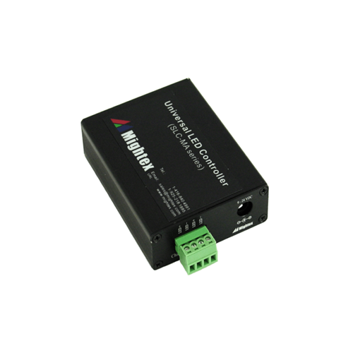
Mightex’s Compact 1- and 2- Channel Computer-Controlled Universal LED Drivers are designed to drive a broad range of LED light sources. Each unit comes with a powerful PC-based software with a user-friendly GUI, which enables users to drive LEDs without the need to write any code. In addition, a full-featured SDK is provided, in order for users to write their own software and to integrate Mightex’s LED drivers into their own systems. Furthermore, the drivers have a built-in protection feature, allowing users to limit LED driving current and voltage. Each channel can be individually configured to work under one of the following two modes: Normal Mode (or DC Mode): The output current is a constant, which can be adjusted (using software) from 0 mA to 1,000 mA, through the USB interface; and Strobe Mode: A Pulse-Width-Modulated (or PWM) periodic strobe pattern is output from the channel, which can be turned on by a software trigger. The strobe pattern may last indefinitely or for a preset number of cycles. The frequency of the PWM strobe can be up to 500Hz. In addition, each channel can be individually DISABLED and ENABLED. No voltage or current is output from a DISABLED channel.
Specifications (Click here to download datasheet)
| Parameters | SLC-MA01-U | SLC-MA02-U | Unit |
| Number of Channels | 1 | 2 | |
| Power Supply Input Voltage (Vdc ) | 9 ~ 24 | V | |
| Maximum Output Voltage (Vmax ) 1 | (Vdc- 3) | V | |
| Maximum Per Channel Output Current (Imax ) | 1000 | mA | |
| Maximum Per Channel Output Power (Pmax ) 2 | 10 | W | |
| Output Current Resolution | 1 | mA | |
| Output Current Accuracy | ±5 mA or ±1.0%, whichever is larger | mA | |
| Output Current Repeatability | ±2 mA or ±0.5%, whichever is larger | mA | |
| PWM Timing Resolution 3 | 100 | μs | |
| PWM Timing Minimum Step Size 3 | 1000 | μs | |
| Interface | USB | ||
1. Maximum Output Voltage is 3V less than the Power Supply Input Voltage. For instance, with a Power Supply Input Voltage of Vdc = 24V, the Maximum Output Voltage Vmax would be (Vdc- 3V) = 21V;
2. If the channel output voltage is Vd and the output current is Id, they must simultaneously satisfy: (1) Vd <= Vmax ; (2) Id <= Imax; and (3) Vd *Id <= Pmax; and
3. Each period of a PWM square wave comprises of ON time and OFF time, i.e. two (2) ‘steps’. The minimum value for each step is 1,000μs, and the minimum increment is 100μs.
4. Proper heat dissipation should be provided to the LED controller in customer’s system in order to prevent over-heating, which may lead to self-shutdown by the LED controller for protection purpose. In addition, the total output current of all channels should not exceed the capacity of the power adapter.
CHANNEL I/O PIN DEFINITION
Each Channel has two pins, defined as following:
| Label | LED+ | LED- |
| Description | LED Anode | LED Cathode |
Product specifications are subject to change without prior notice. All prices are FOB California, unless otherwise stated. Please call/email for volume pricing.
상품의 사용후기를 적어주세요.
게시물이 없습니다
상품에 대해 궁금한 점을 해결해 드립니다.
게시물이 없습니다


법인명(상호) : 유니나노텍(주) 대표자(성명) : 유니나노텍(주) 사업자 등록번호 안내 : [1428150860] 통신판매업 신고 2021-용인기흥-0779 [사업자정보확인]
전화 : 031-546-8733 팩스 : 주소 : 17015 경기도 용인시 기흥구 동백중앙로16번길 16-4 (중동) 에이스동백타워 1동 303호
개인정보보호책임자 : 유니나노텍(주)(nano@uninanotech.com)
Contact for more information.
Copyright © 유니나노텍(주). All rights reserved. hosting by cafe24 카페24(주)